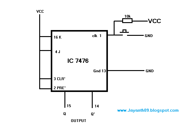
Jk Latch Circuit Diagram
Solved the jk latch is wired as the following: a b nor 1 1 Draw jk flip flop using cmos and explain the working. Jk flip flop circuit using 74ls73
JK Flip Flop Circuit using 74LS73 - Truth Table
Latch nor Jk flop proteus circuit Jk latch truth table experiment guide circuit sparkfun learn logic something looks
Latch jk sequential
F-alpha.net: experiment 26Latch using jk flip flop Plc latching logic latch ladder gate latched contacts instrumentationtools instrumentationPlc latching function.
Jk latch gated circuit flip flop electronics experiment diagram digital enable alphaLogicblocks experiment guide D-latch, jk latch, t latchJk latch flop.

Flop jk circuit truth logic sequential bcis bistable
J-k flip-flop and t-flip-flop || sequential logic || bcis notesFlip jk flop cmos using latch draw gate transmission explain comment add working Jk flip flop circuit diagram in proteusFlip flop jk circuits.
.


