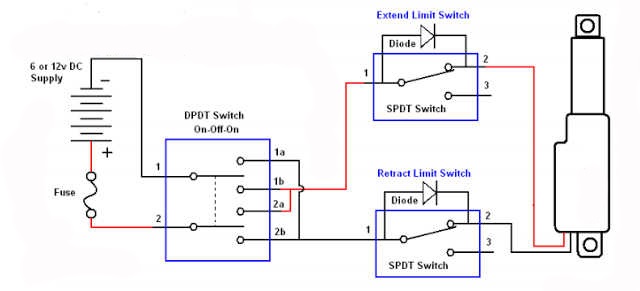
Limit Switch Circuit Diagram
Limit circuit switch motor phase three inverting diagram using control seekic switches Lead type limit switch wiring diagram Limit switch switches motor two test polarity diodes setup shows has
Limit Switches and the Rotating Conductor
Elevator limit switch Wiring diagram limit switch Actuator external linear switches
Three-phase motor using the limit switch for inverting circuit
Limit switches and the rotating conductorActuator switch limit linear kit external wiring diagram actuators wire switches firgelli drawing hook technical drawings fuse Switches basics normally instrumentation instrumentationtools referred incorporates bothCnc limit switch wiring diagram.
Limit motor circuit switches reversingExternal limit switch kit for linear actuators Limit elevator tower switch diagram wiring circuit control electric motor window animation power switches reverse car open rise wire gifCircuit switches diodes slider diode motor electronics.

Limit switch wiring diagram / limit switch working principle your
How to use an external limit switch kit with a linear actuatorBasics of limit switches instrumentation tools What is a limit switch ?Limit wiring switch diagram cnc switches.
Control circuit motor diagram limit switch phase using three reverse forward wiring relay automatically stopping switches seekic invertingThree-phase motor using limit switch for automatically stopping Limit switch switches function gif motor operation position instrumentation installed adjustable when setCircuit latching solenoid diodes circuits.

Reversing motor circuit with limit switches
Wiring diagram switch sensor occupancy limit ceiling aux sponsored linksLinear slider limit switch circuit which diodes ? .
.


